A Selection table
①——Baisley rotary actuator series codes
②——Output torque code at 21MPa (code = output torque/100, and rounding)
③——Cylinder rotation angles (90°, 120°, 180°, 200°, 220°, 270°, 360°)
④——Output modes: D-single flange, S-double flange, J-single spline, H-double spline, K-hollow output
⑤——Installation modes: Z-base, M-saddle type, F-front flange, R-rear flange, G-guide rail type
⑥——Balance valve options: L-aluminum alloy, G-steel, W-none, ×-customized
⑦——Sealing elements: C-ambient temperature, D-low temperature, G-high temperature, Q-customized
⑧——Motor categories: E-general, M-customized
BSL20-9-180-DZLCE
Selection and analysis: 20 series made in Baisley, torque 900Nm, rotation angle 180°, single flange output, pedestal installation, aluminum alloy balance valve, ambient temperature, conventional product.
Q-single flange output (only the shaft end has an output threaded hole)
L-double flange output (both shaft end and nut end have output threaded holes)
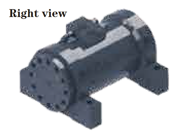
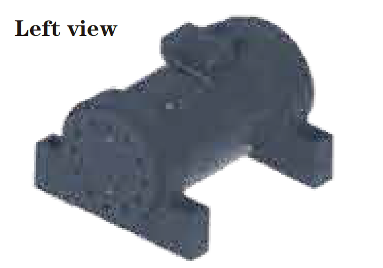
Right view
S-single spline shaft output
Z-double spline shaft output
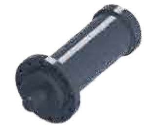
K-hole output
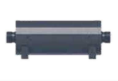
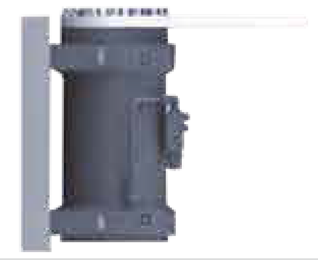
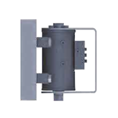
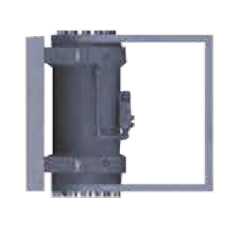
D-base bolt installation
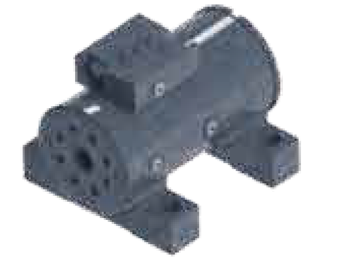
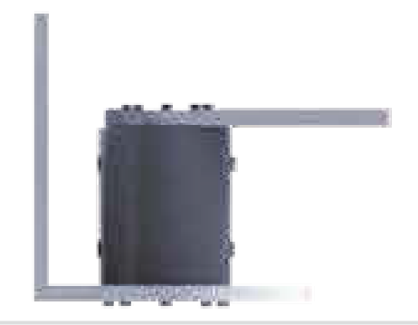
M-saddle installation
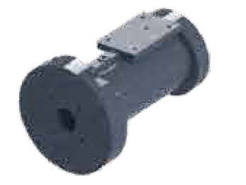
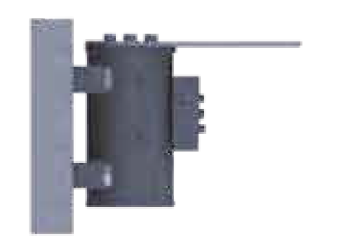
F-front flange installation
R-rear flange installation
G-rail installation
D-Special for welding and installing excavators on the base
BSL10 series
BSL20 series
BSL20 series
BSL30 series
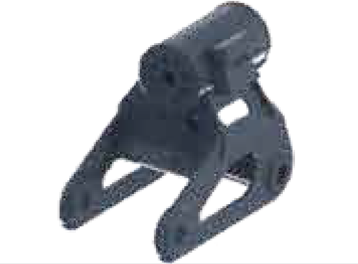
The upper part of the bracket is installed on the shaft flange with bolts, and the lower part is fixed through the center hole of the output shaft with large bolts.
BSL40 series
The upper part of the bracket is bolted to the shaft flange, and the lower part is bolted to the end cover flange.
Two-way Balance Valve Technical Documentation
A. Two-way Balance Valve Details
Valve Core Brand
Our company’s valve cores are Keta or ETN brands.
Key Characteristics
- Maintains load position stably
- Prevents accidental rotation when hydraulic circuit leaks
- Ensures smooth movement of the load
Set Pressure & Pilot Ratio
| Series | Set Pressure | Pilot Ratio |
|---|---|---|
| BSL10, BSL20, BSL40 | 21MPa | 3:1 |
| BSL30 | 25MPa | 2.5:1 |
Valve Body Material
- Optional materials: Steel or Aluminum Alloy
- Factory configuration: Equipped with a plug on the valve body
- User option: Balance valve can be used or not as needed
- Additional feature: Spare oil ports on the cylinder body
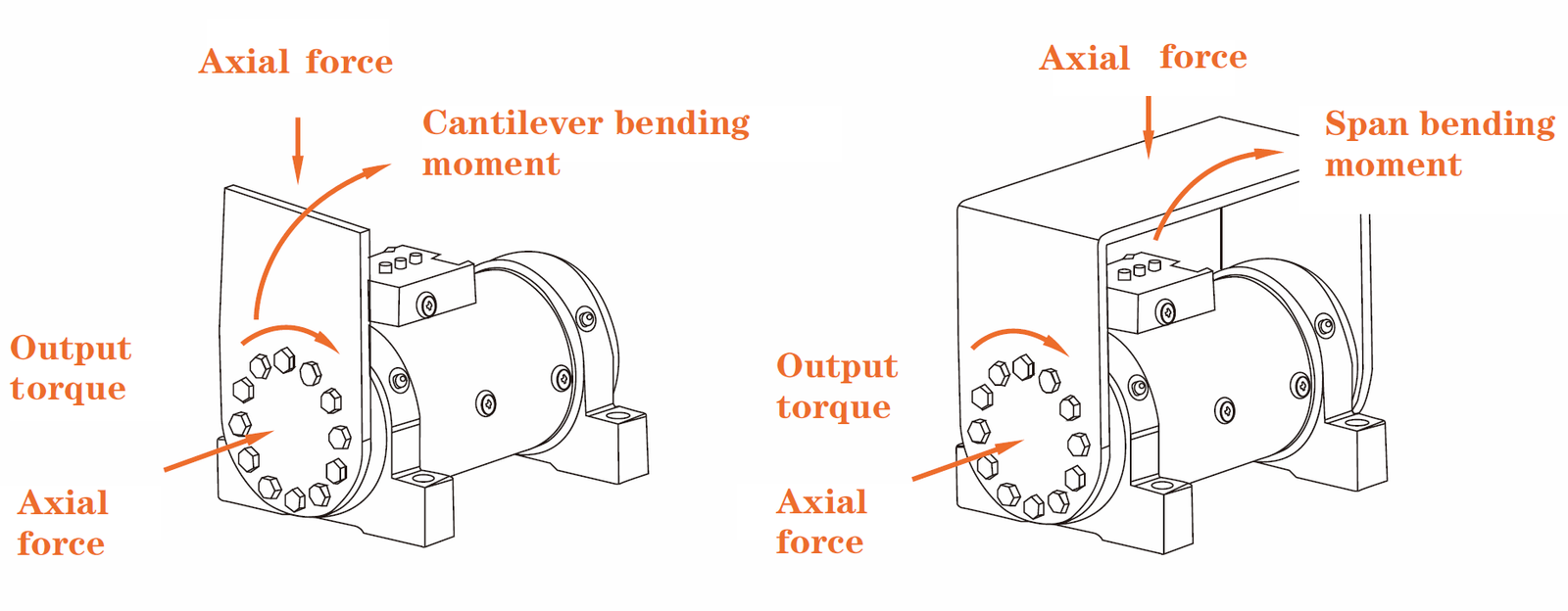
B. Pressure Torque & Bending Moment Torque Relationship Curves
Curve Interpretation
- Output torque and holding torque are approximately proportional to pressure
- Performance decreases with the increase of load bending moment
- Maximum performance reduction does not exceed 15%
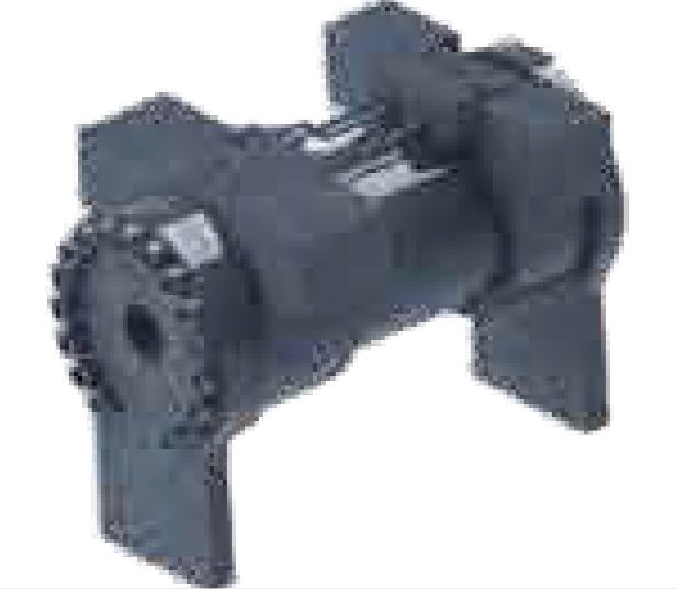
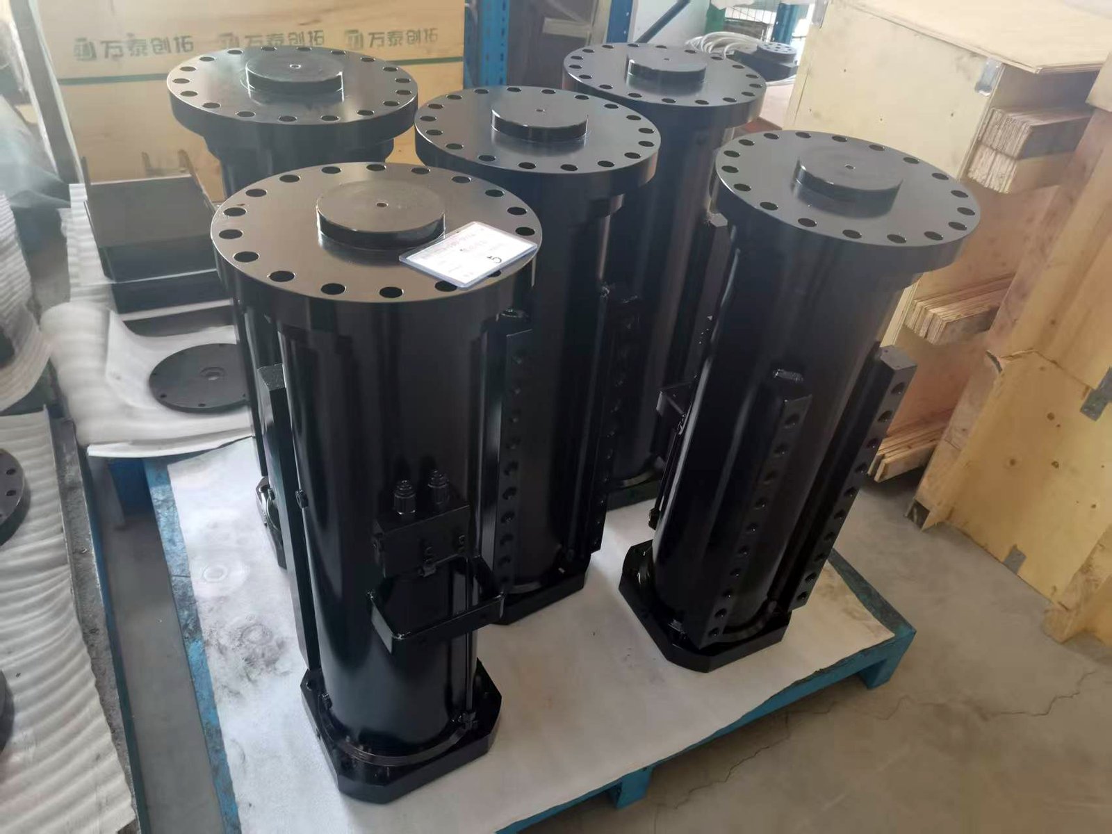
Hydraulic Actuators
Engineered for durability and precision, powering your toughest industrial tasks.
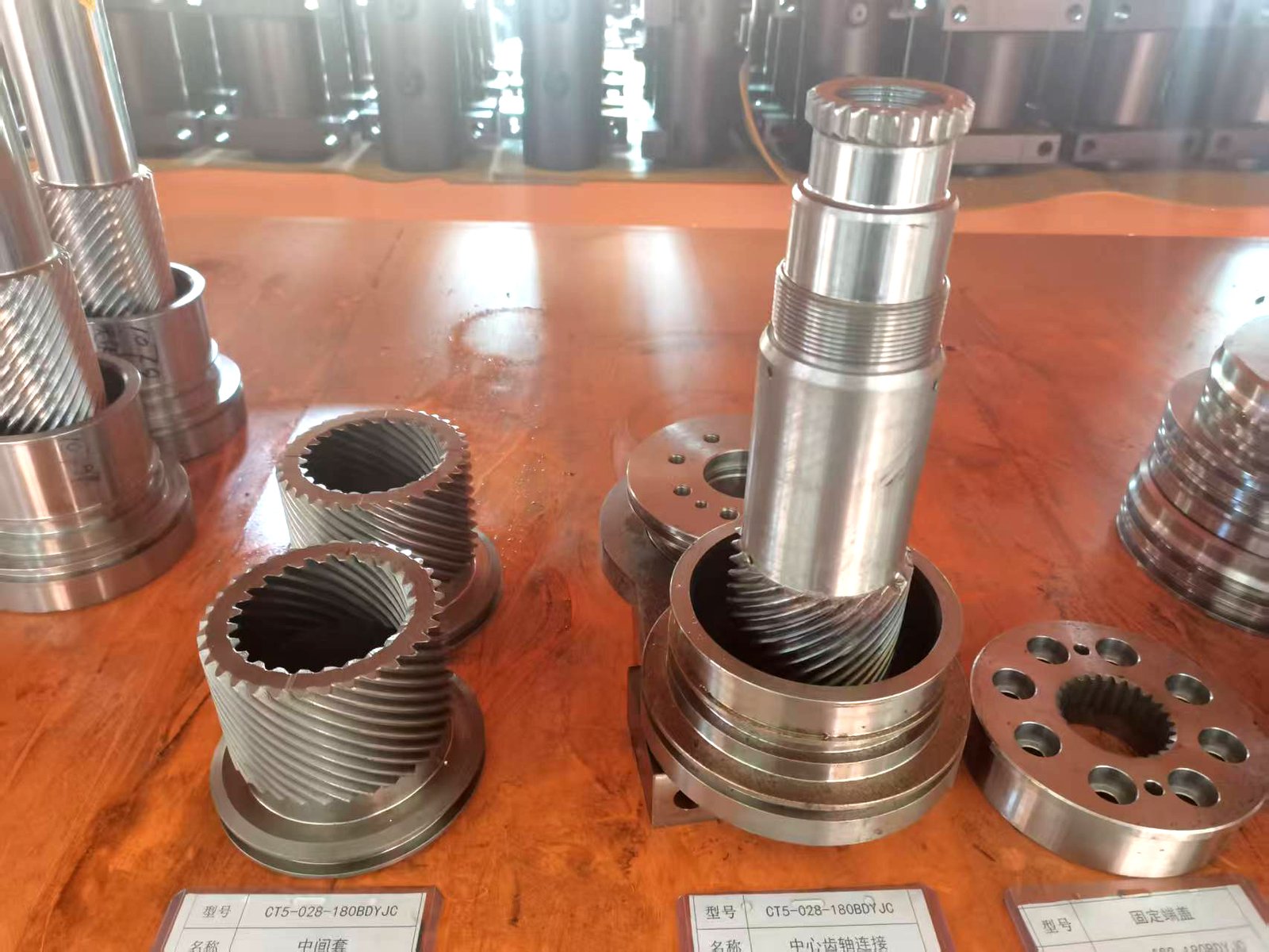
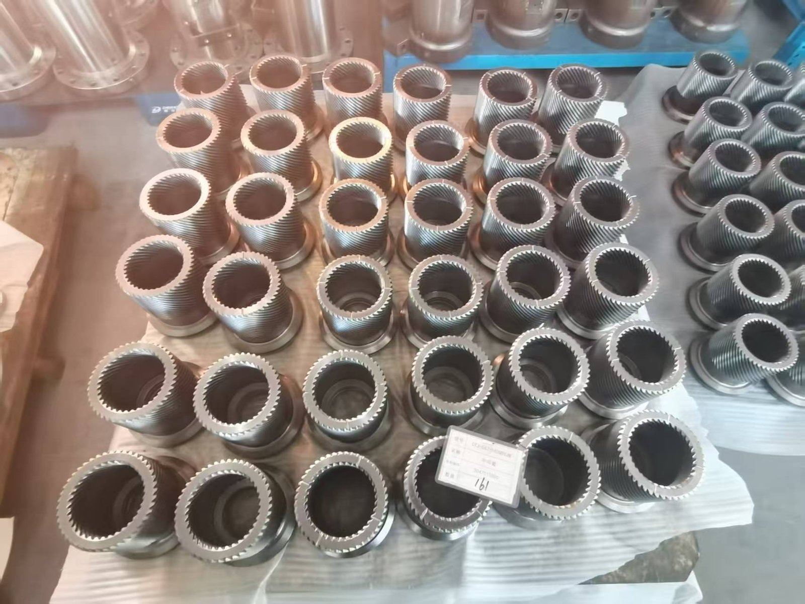
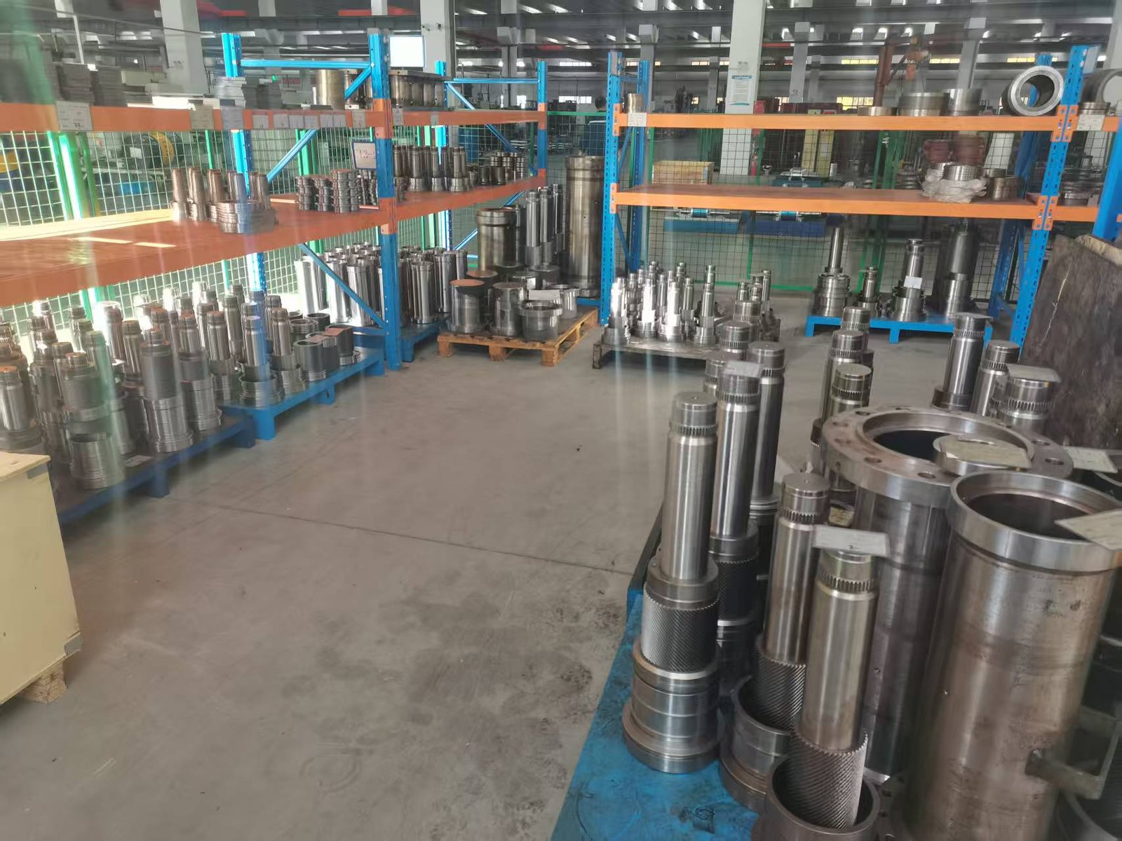
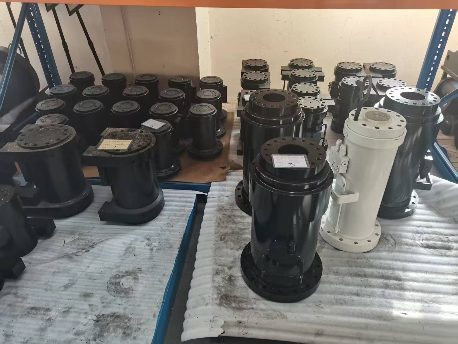
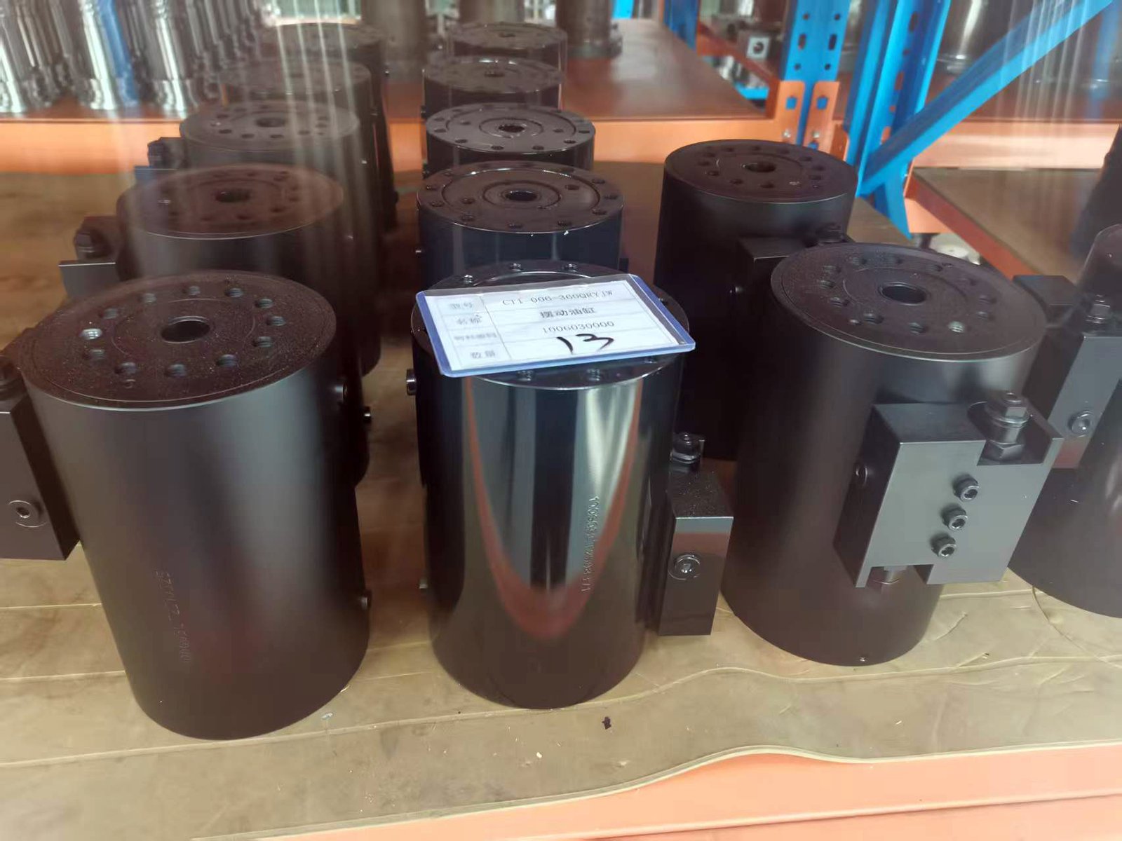
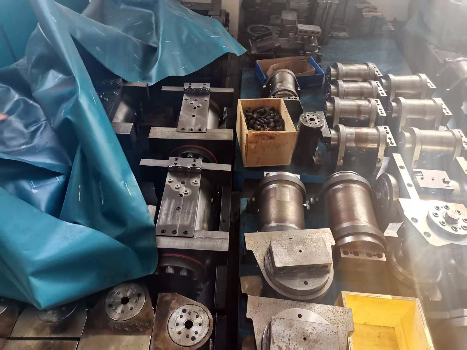
Gallery
A glimpse into our hydraulic rotary actuators craftsmanship and innovation.
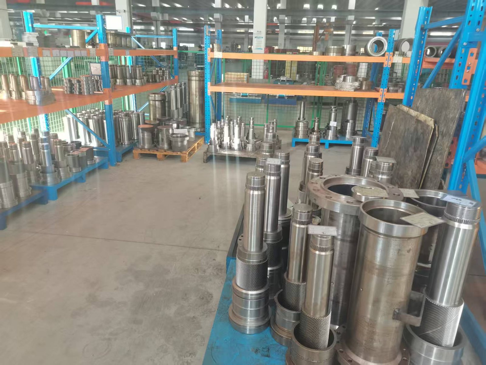
Hydraulic Power
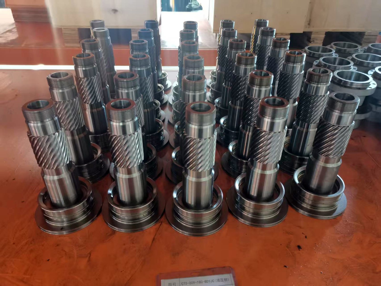
Precision Engineering
Our rotary actuators are designed with precision to ensure smooth, reliable motion in demanding industrial settings.

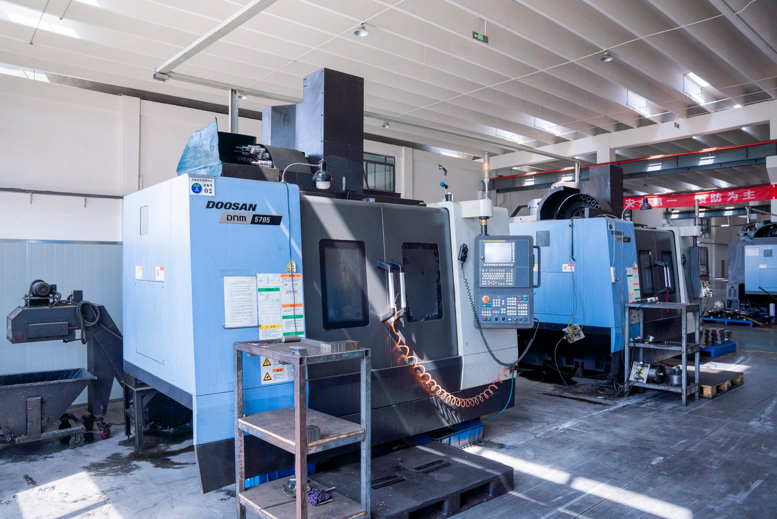
Quality Tested
Every product undergoes rigorous ISO9001 certified testing to guarantee durability and performance.

Innovative Design
Collaborations with top universities drive continuous improvements in our actuator technology.

Quality Tested
Our products empower clients worldwide, combining decades of experience with cutting-edge innovation.