B
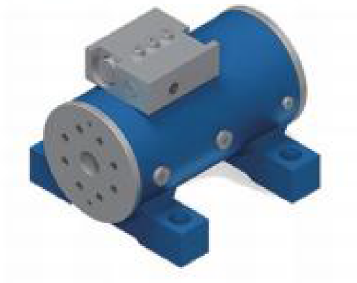
BSL20 series
- Standard output angle 180 degrees
- Output torque 500——4200NM
- Holding torque 1300——10500NM
- Straddle bending moment load 2500——31600NM
- Cantilever bending moment load 1360——15800NM
- Installation mode Anchor type
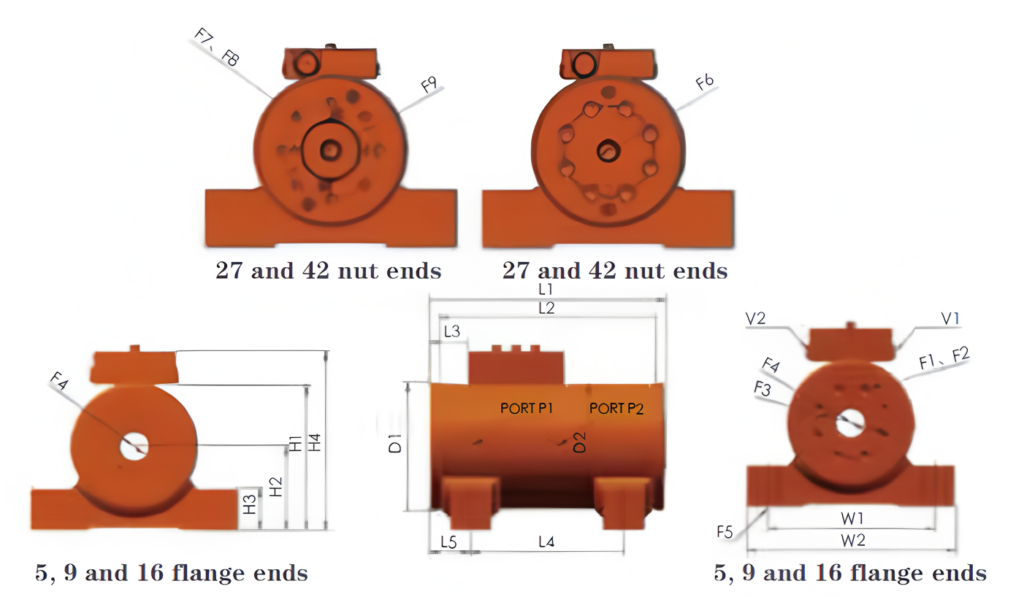
BSL20 series size table
| Model < | 5 < | 9 < | 16 < | 27 < | 42 |
|---|---|---|---|---|---|
| Output torque Nm@21MPa | 500 | 900 | 1600 | 2680 | 4200 |
| Save torque Nm@21MPa | 1300 | 2400 | 4400 | 7100 | 10500 |
| Maximum bending moment of straddle installation Nm | 2500 | 4500 | 10200 | 16400 | 31600 |
| Maximum bending moment of cantilever installation Nm | 1360 | 2480 | 5420 | 11300 | 15800 |
| Radial load kg | 1380 | 2130 | 4190 | 5580 | 9530 |
| Axial load kg | 500 | 680 | 1000 | 1400 | 1770 |
| The displacement is 180 degrees ce | 132 | 234 | 436 | 726 | 1070 |
| Weight kg | 12.5 | 17 | 30 | 51 | 77 |
| D1 Installation disk diameter mm | 104 | 117 | 142 | 170 | 196 |
| D2 Shell diameter mm | 101 | 114 | 139 | 165 | 191 |
| F1 Flange end screw hole size mm | M10 x1.5 | M10 x1.5 | M12 x1.75 | M20x2.5 | M20x2.5 |
| F2 Number of screw holes at flange end | 6 | 8 | 8 | 8 | 10 |
| F3 Diameter of central circle of flange end screw mm | 53.9 | 65 | 85 | 102 | 121 |
| F4 Size of inner shaft through hole mm | M20 | M24 | M24 | ||
| F5 Matching bolt size for foot mounting hole mm | M16 | M20 | M24 | M24 | M30 |
| F6 Axis center hole size mm | M24x3 | 11/4-7 | |||
| F7 Dimensions of nut end screws mm | M12 x1.75 | M16x2 | |||
| F8 Number of nuts end screws | 8 | 10 | |||
| F9 Diameter of central circle of screw hole at nut end mm | 108 | 121 | |||
| H1 Height of balance valve is not included. mm | 119 | 135 | 158 | 193 | 218 |
| H2 Height of bottom surface from center line mm | 66 | 76.2 | 85.9 | 108 | 121 |
| H3 Foot height mm | 34.3 | 38.1 | 44.5 | 63.5 | 70 |
| H4 Total height mm | 146 | 163 | 185 | 220 | 245 |
| L1 Total length mm | 188 | 216 | 248 | 298 | 337 |
| L2 Length of rotating flange is not included. mm | 173 | 197 | 229 | 276 | 314 |
| L3 Distance between flange and balance valve mm | 32 | 34.5 | 44.7 | 48.8 | 49 |
| L4 Foot mounting hole spacing mm | 111 | 140 | 152 | 184 | 216 |
| L5 Distance between flange and mounting hole mm | 37.9 | 37.6 | 47 | 57.2 | 60.5 |
| W1 Foot mounting hole spacing mm | 145 | 152 | 197 | 222 | 267 |
| W2 Total width mm | 178 | 191 | 248 | 279 | 330 |
| P1/P2 Shell oil port | ISO-1179-LBSPPG series with dimensions ranging from 1/8 to 1/4. See the drawing for details. | ||||
| V1/V2 Valve body oil port | ISO-11926/SAE series, with a dimension of 7/16. See the drawing for details. | ||||
According to the production design requirements, the parameters and dimensions may be changed.
Please refer to the drawings for the exact parameters and dimensions.
Please refer to the drawings for the exact parameters and dimensions.