A
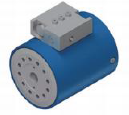
BSL10 series
- Standard output angle 180, 360 degrees
- Output torque 180——2700NM
- Holding torque 630——9400NM
- Cantilever bending moment load 560——11200NM
- Installation mode Flange type
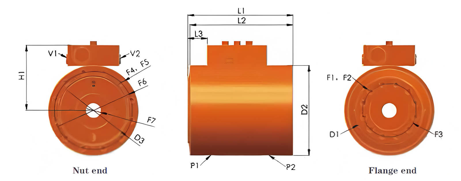
BSL10 series size table
| Output torque Nm@21MPa | |||||||
|---|---|---|---|---|---|---|---|
| Model | 1 | 2 | 3 | 6 | 10 | 16 | 27 |
| Output torque Nm@21MPa | 180 | 320 | 600 | 1000 | 1600 | 2700 | |
| Save torque Nm@21MPa | 630 | 1200 | 1900 | 3800 | 5700 | 9100 | |
| Maximum bending moment Nm | 560 | 1000 | 2200 | 5600 | 9000 | 14200 | |
| Radial load kg | 900 | 1350 | 1850 | 3600 | 4890 | 6700 | |
| Axial load kg | 600 | 1210 | 1820 | 3600 | 4590 | 6170 | |
| The displacement is 180 degrees cc | 99.9 | 135 | 195 | 365 | 582 | 904 | |
| The displacement is 360 degrees cc | — | 243 | 384 | 733 | 1105 | 1829 | |
| Weight (180°) kg | 6.4 | 10 | 14.2 | 36 | 43.3 | 87 | |
| Weight (360°) kg | — | 12.8 | 19.2 | 35 | 54.5 | 83 | |
| D1 Shell diameter mm | 72 | 89 | 105 | 127 | 148 | 185 | |
| D2 Installation disc diameter mm | 100 | 119 | 132 | 170 | 196 | 226 | |
| F1 Flange end screw hole size mm | M8×25 | M8×25 | M10×5 | M12×7.5 | M12×7.5 | M16×8 | |
| F2 Number of central holes at Flange end | 4 | 8 | 12 | 12 | 12 | 12 | |
| F3 Diameter of screw hole circle at Flange end screw mm | 84 | 93 | 102 | 102 | 127 | 140 | |
| F4 Number of screws at nut end mm | M8×25 | M8×25 | M10×5 | M12×7.5 | M12×7.5 | M12×7.5 | |
| F5 Dimensions of nut end screws | 8 | 8 | 12 | 12 | 12 | 12 | |
| F6 Diameter of central circle of screw hole at nut end mm | 86 | 103 | 117 | 151 | 175 | 203 | |
| F7 Installation hole diameter mm | 14.3 | 17 | 21.4 | 35.7 | 45.7 | 66.7 | |
| H1 Central hole to valve body size mm | 40 | 43 | 58 | 115 | 129 | 141 | |
| L Total length (180°) mm | 180 | 190 | 196 | 314 | 324 | 343 | |
| L1 Length of rotating flange is not included. (180°) mm | 138 | 149 | 152 | 258 | 271 | 296 | |
| L2 Total length (360°) mm | — | 182 | 214 | 282 | 311 | 340 | |
| L2 Length of rotating flange is not included. (360°) mm | — | 158 | 211 | 256 | 308 | 344 | |
| L3 Distance between flange and balance valve length (180°) mm | 25.4 | 26.9 | 27.7 | 27.9 | 38.6 | 43.9 | |
| L3 Distance between flange and balance valve length (360°) mm | — | 22.6 | 24.6 | 42.7 | 60.8 | 70.4 | |
| P1/P2 Shell oil port | ISO 1179-2:2008 “G” series, with a dimension of 7/8″. See the drawing for details. | ||||||
| V1/V2 valve body oil port | ISO 1179-2:2008 “A” series, with a dimension of 7/8″. See the drawing for details. | ||||||
* According to the production design requirements, the parameters and dimensions may be changed. Please refer to the drawings for the exact parameters and dimensions.